In the field of industrial automation and energy management, relays play a crucial role in ensuring the switching and control of electrical circuits. Among the various types of relays available, solid-state relays (SSRs) stand out due to their lack of moving parts, offering extended lifespan and increased reliability. This article aims to explore the operation of solid-state relays, their advantages, and the applications in which they excel, to provide the reader with an in-depth understanding of this innovative technology.
The Origins of Solid-State Relays
Solid-state relays trace their origins to the technological advancements in semiconductors in the mid-20th century. While electromechanical relays traditionally dominated the electrical switching market, the emergence of transistors and thyristors paved the way for a new generation of switching devices without moving parts. Early solid-state relays utilized thyristors, such as SCRs (Silicon Controlled Rectifiers), to manage current switching. These components enabled faster and quieter switching while reducing mechanical wear. Over time, advancements in semiconductor technology led to the integration of MOSFETs and triacs, further enhancing the performance and reliability of solid-state relays. Today, SSRs are widely used in various industrial and commercial applications due to their ability to provide reliable and efficient switching.
What is a Solid-State Relay (SSR)?
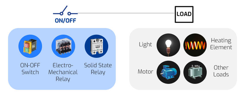
A solid-state relay is an electronic component that provides an interface with electrical isolation between a control circuit, typically low-level, and a power circuit connected to loads that may have high rated power (motors, pumps, solenoid valves, heaters, etc.). In other words, it is an electrical component used to turn a load on and off. This function is performed entirely “statically,” without moving parts, thus giving the component an almost unlimited lifespan.
The Structure of a Solid-State Relay
The solid-state relay, also known as SSR, is composed of five main functions. Its structure is technically equivalent and comparable to that of an electromechanical relay (EMR).
- The Input Circuit – In an electromechanical relay, the input characteristics (voltage, current, level) are determined by the coil. Similarly, a solid-state relay has an input circuit of varying complexity. In lower-end models, it might consist of a simple series resistor with a polarizing diode. More complex relays may include a circuit generating a constant current for extended input voltage ranges or an analog-to-digital converter for analog relays.
- Isolation – In an electromagnetic relay, the electromagnetic coupling between the moving armature and the coil naturally provides galvanic isolation. In a solid-state relay, this isolation is ensured by optical coupling (phototransistor, phototriac, etc.). In some older versions, isolation may be provided by magnetic coupling or even a reed relay.
- The Trigger Circuit – This circuit processes the received input signal and switches the output circuit. When the switching is complex (zero-voltage switching, pulses, phase control, etc.), this circuit ensures the desired switching mode. For example, in zero-voltage switching, the circuit ensures that the output will only switch when the voltage returns to zero after the control input is applied.
- The Switching Circuit – This circuit consists of an element that switches the electrical supply to the load. This component can be a bipolar transistor or a MOS transistor for switching DC voltage to the load, or a triac or coupled thyristors for switching AC power. In an electromechanical relay, the switching element is a simple contact that can operate in either AC or DC mode. In a solid-state relay, the output predetermines the type of main power supply being switched.
- The Protection Circuit – Due to their entirely electronic structure, solid-state relays are more sensitive to electrical network interference than electromagnetic relays. The switching circuit must be protected against voltage surges and low-voltage supply interference. Increasingly, relays integrate this protection. Protection against voltage surges is now standard.
How to Verify the Proper Operation of a Solid-State Relay (SSR)?
The solid-state relay, also known as SSR, is composed of five main functions. Its structure is technically equivalent and comparable to that of an electromechanical relay (EMR).
- Visual Inspection:
- Check for any physical damage on the SSR, such as cracks or burns.
- Ensure that connections are tight and there are no signs of corrosion.
- Continuity Test:
- Use a multimeter to check continuity between the output terminals of the SSR when it is activated. There should be continuity (near-zero resistance) when the SSR is activated and infinite resistance when it is deactivated.
- Control Test:
- Apply the appropriate control voltage to the SSR’s control terminals and verify that the relay activates correctly.
- Ensure that the SSR deactivates when the control voltage is removed.
- Load Test:
- Connect an appropriate load (such as a lamp or motor) to the SSR’s output terminals and activate it.
- Verify that the load operates correctly when the SSR is activated and stops when it is deactivated.
- Voltage Drop Measurement:
- Measure the voltage across the SSR’s output terminals when it is activated and under load. A high voltage drop may indicate an issue with the internal semiconductor component.
- Temperature Test:
- Check that the SSR does not overheat during operation. Overheating may indicate a thermal dissipation problem or overloading.
- Protection Circuit Verification:
- Ensure that protection devices, such as fuses or circuit breakers, are properly sized and functional.
What is the Purpose of Solid-State Relays in Industry?
Solid-state relays (SSRs) stand out for their ability to provide reliable and wear-free switching, making them a preferred choice in many industrial applications. Thanks to their semiconductor-based technology, SSRs enable precise and efficient control of electrical circuits, meeting the demands of modern industrial environments. From temperature management to process automation, lighting control, and energy management, solid-state relays find their place in a multitude of sectors. Let’s explore some concrete examples where SSRs demonstrate their added value and contribute to improving the performance and efficiency of industrial systems.
Examples of Industrial Applications

Temperature Control
SSRs are commonly used in heating, ventilation, and air conditioning (HVAC) systems to regulate temperature by controlling heating elements or compressors.

Motor control
SSRs can be used to start and stop electric motors, offering a reliable and maintenance-free solution compared to electromechanical relays.

Control Lighting
Solid-state relays are used to control lighting in industrial environments, providing wear-free switching and a long lifespan for lighting components.

Energy management
Solid-state relays are used in energy management systems to control electricity distribution, thereby optimizing energy consumption and reducing costs.
A Wide Range of Solid-State Relays
Crouzet, a leader in control and automation solutions, offers a wide range of solid-state relays (SSRs) designed to meet the diverse needs of industrial applications. Their SSRs stand out for their reliability and performance, providing precise switching without moving parts, ideal for temperature control, process automation, and lighting management. Incorporating the latest advancements in semiconductor technology, these relays ensure increased responsiveness and enhanced protection against voltage surges. Easy to install and compatible with various control systems, Crouzet’s solid-state relays undergo rigorous testing to ensure their durability and efficiency under varied operating conditions. By choosing Crouzet, professionals benefit from tailored and high-performing solutions, backed by decades of expertise and innovation.
The SSRs Offered by Crouzet
SINGLE-CHANNEL
Classic single relays available in multiple formats for any type of application
MULTI-CHANNEL
2 or 4 relays in one single package for space-saving needs
LOAD DIAGNOSTICS
Single relays and add-on modules with load monitoring functions for heating systems
AC 3-PHASE
Solid-state contactors for 3-phase heaters and motor control
DC OUTPUT
DC relays to control motors, lighting and other applications working on a DC power supply
Discover more
All news
AC or DC Driver? Which Choice for Automatic Barriers?
In the field of railway safety, automatic barriers at level crossings play a crucial role in…
AC vs DC Motors: Understanding the Differences to Choose the Right Motor
In the world of electromechanics, electric motors play a crucial role in converting electrical energy into…

RCC-E 2012 and Crouzet limit switches
In the nuclear sector, the reliability of electrical equipment is a crucial issue. Every component used…

Weight on wheels proximity switches
Weight on wheels (WoW) switches indicate whether the weight of an aircraft is resting on its…